An illustrated centrifugal pumps handbook for engineers and maintenance teams, with worked examples and references:
(Multistage) centrifugal pumps construction · operating principle · types · spotting and preventing cavitation and air binding
Key Takeaways
- Principle in one sentence: a motor spins the impeller, which transfers mechanical energy to the liquid; the volute (or diffuser vanes) then converts the liquid’s velocity head into pressure head.
- Two classic problems: cavitation (local pressure falls below the liquid’s vapor pressure, forming bubbles that collapse) and air binding (gas trapped in the pump so it cannot draw liquid). Their causes, symptoms and cures are different.
- One selection rule: the system’s NPSH available (NPSHA) must exceed the pump’s NPSH required (NPSHR) with a margin; NPSHA only slightly above NPSHR does not guarantee cavitation-free operation.
- One operating rule: keep the pump within roughly 70%–120% of its best efficiency point (BEP) flow (narrower for some high specific speed pumps).
- One maintenance rule: replace wear rings when running clearance reaches about twice the new minimum, or when performance has clearly dropped.
- Multistage pumps: several impellers in series on one shaft, with total head about the sum of the stage heads; the keys are axial-thrust balancing (opposed impellers or a balance drum / disc) and interstage clearances.
1. What A Centrifugal Pump Is
A centrifugal pump is a rotodynamic machine: a spinning impeller adds energy to the liquid passing through it. It is used in chemical plants, refineries, power stations, municipal water and wastewater systems, irrigation and HVAC. It is popular because it is mechanically simple, delivers a smooth continuous flow, covers a wide range of duties, is compact, and is relatively cheap to buy and run. Its limits are just as important: it generally cannot self-prime, loses efficiency on viscous liquids, and becomes less efficient and less reliable when operated far from its design point.
This guide keeps the classic flow of “construction → principle → classification → cavitation / air binding”, and adds selection and maintenance notes, worked calculations, start-up checklists and troubleshooting tables. A few popular but loose statements are tightened up in Section 10.
2. How It Works in Four Steps
- Prime the pump. The casing and suction line must be full of liquid before start-up. The impeller moves liquid, not air; gas in the pump leads to air binding.
- The impeller does the work. The impeller turns at high speed and the vanes drive the liquid round with it. Centrifugal action throws liquid from the impeller eye to the rim, raising both its pressure and its velocity.
- The volute recovers pressure. The liquid enters a casing passage whose cross-section grows steadily; velocity falls and most of the kinetic energy becomes pressure before the liquid leaves through the discharge.
- Suction refills the eye. As liquid is thrown outward, pressure at the impeller eye drops. The difference between the pressure on the supply liquid surface (atmospheric, for an open tank) and the pressure at the eye pushes liquid up the suction line and keeps the cycle going.
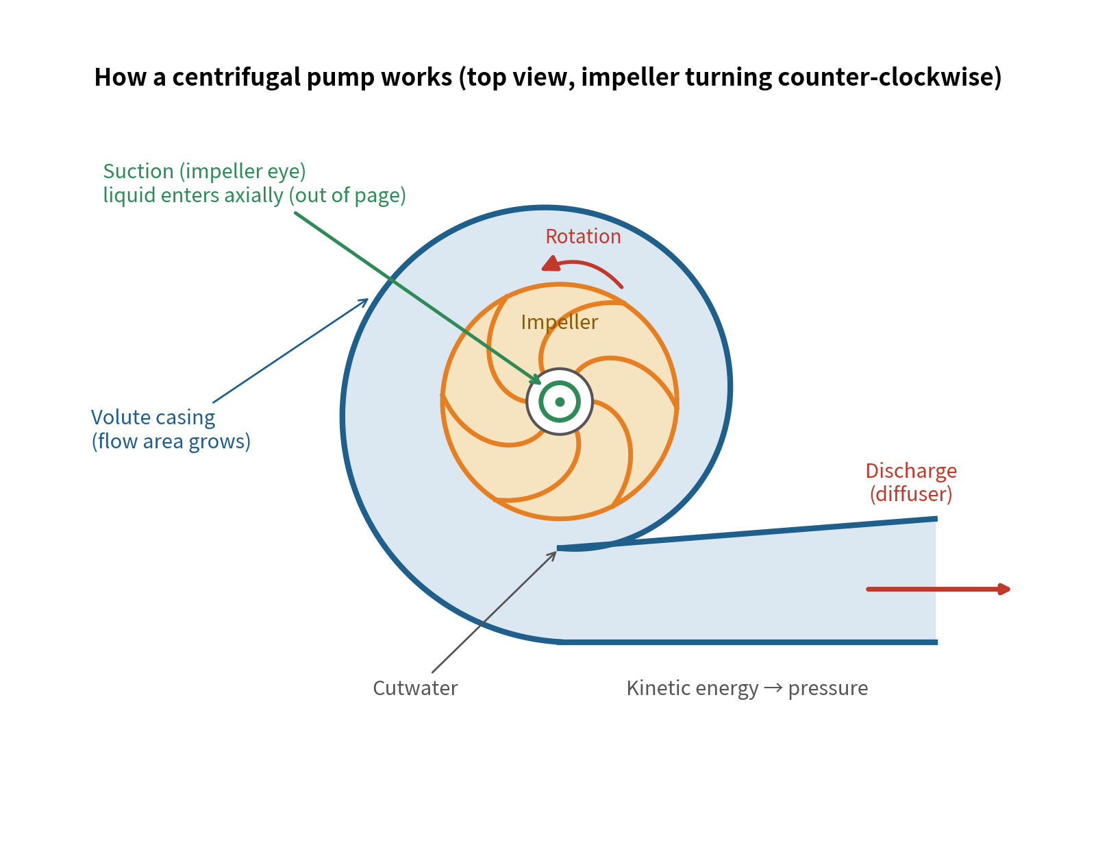
Figure 1. How a centrifugal pump works
Quick calculation — impeller tip speed: u = π·D·n / 60. For D = 0.20 m and n = 2,900 rpm, u ≈ 30.4 m/s. Single-stage head rises roughly with the square of tip speed, which is why speed or impeller diameter changes have such a strong effect on head (see the affinity laws in Section 8).
Common misconception: is the impeller eye a “vacuum”?
Saying the impeller centre is a vacuum is shorthand. What actually happens is that pressure at the eye is reduced (it may fall below atmospheric, but it is not a vacuum). How high a pump can lift liquid depends on atmospheric pressure, the liquid’s vapor pressure, suction-line losses and the pump’s own NPSHR, not on “how much vacuum” it creates. When pressure falls to the vapor pressure, cavitation begins (Section 6). [3][4]
3. Construction and Component Notes
Centrifugal pumps look very different from one another, yet their main parts are the same: impeller, shaft, casing (volute), bearings and bearing housing, shaft seal, wear rings, and — in multistage pumps — diffusers (guide vanes). The table is a quick reference.
Part
Main Function
Typical Materials
Typical Failures / What to Watch
Impeller
Shaft
Shaft Sleeve
Bearings
Shaft Seal
Casing (Volute)
Diffuser (Guide Vanes)
Wear Rings
3.1 Impellers: Three Constructions and Their Trade-Offs
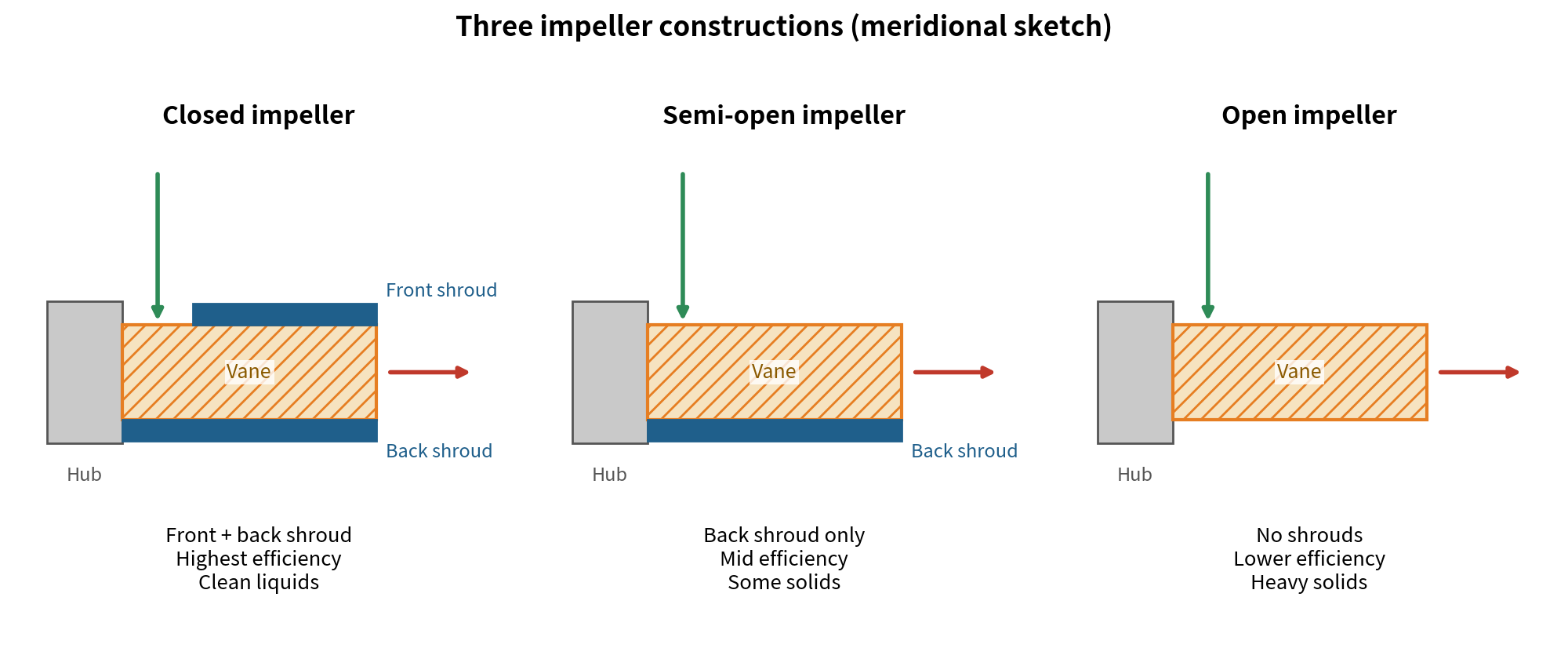
Figure 2. Closed, semi-open and open impellers
Type
Construction
Efficiency / Suitable liquids
Notes
Closed
Semi-Open
Open
Note: solids-handling impellers use fewer vanes (commonly one to four) to keep the passages large, while clean-water closed impellers usually have more; vane count varies with design, so avoid treating any one number as a rule. [18]
3.2 Shaft, Sleeve and Bearings
- Axial location: the key transmits torque but does not fix the impeller axially, so a shaft sleeve and lock nut are used to locate it.
- Prevent reverse rotation: where the lock nut is retained by thread direction, reverse rotation can loosen it. After first assembly or any overhaul, confirm motor rotation matches the arrow on the pump (normally by bumping the motor with the coupling disconnected).
- The sleeve is a wear part: with gland packing, the sleeve takes the rubbing and is often surface-hardened. Replace a grooved sleeve; no amount of gland tightening will stop leakage past it. [16]
- Bearings: rolling-element bearings dominate. Lubricant cleanliness and level are the biggest drivers of life; follow the manufacturer’s drawings and the bearing catalogue for fits and clearances.
3.3 Shaft Seals: Packing or Mechanical Seal?
Where the shaft leaves the casing, the pump must be sealed — otherwise pressurised liquid escapes along the shaft, and on the suction side air may be drawn in. The two common solutions are:
Aspect
Gland Packing
Mechanical Seal
Principle
Leakage
Friction / Power
Effect on Shaft
Failure Behaviour
Cost / Upkeep
Typical Use
Packing tips: too loose and leakage becomes excessive; too tight and the packing can burn up at start-up and score the sleeve. If a flush is used, it should be clean and slightly above stuffing-box pressure. [15][16]
3.4 Casing: Volute, Double Volute and Diffuser
Converting the impeller’s velocity head into pressure is done either by a volute (a spiral passage of growing area) or by a diffuser (stationary vanes around the impeller forming diverging passages). The volute is easy to manufacture, has a broad high-efficiency range, and is the most common form. [5][8]
The radial-load issue: a single volute gives uniform pressure around the impeller only near the best efficiency point. Away from BEP the pressure becomes uneven and loads the impeller and shaft radially, which can bend the shaft and shorten bearing and seal life. HI notes that radial thrust is lowest near BEP and higher at both reduced and increased flows. [6] Remedies include a double volute (two cutwaters 180° apart so the two radial forces largely cancel), a diffuser, or a stiffer shaft with larger bearings. [5][8]
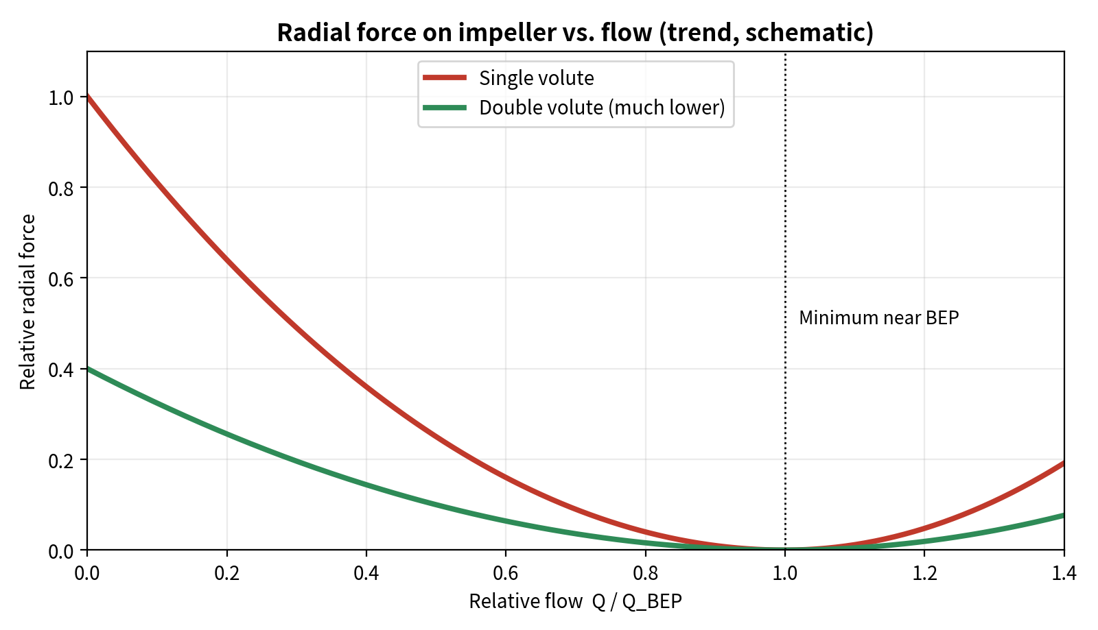
Figure 3. Trend of radial force with flow (schematic). A double volute greatly reduces, but does not eliminate, radial force.
One experimental study (a test pump at 500–900 rpm) reported that, compared with a single volute, a double volute cut radial thrust by more than 55% at shut-off and more than 40% at high discharge — but the best efficiency was still obtained with the single volute. [7] Industry sources likewise note that radial forces in a double volute are “greatly reduced, not completely eliminated”, and that its splitter vane can cause blockage with solids such as in wastewater. [5] In multistage pumps a common arrangement is volute casings at the first and last stages with diffusers in between; diffuser casings are easier to manufacture and convert energy slightly more efficiently, but they are harder to assemble and service.
3.5 Wear Rings: Tiny Gaps, Big Effect
Wear rings sit at the impeller eye (and sometimes on the back shroud) and use a very small clearance to limit leakage from the high-pressure side back to suction. A smaller gap means less internal leakage and higher efficiency, but too small a gap risks rubbing and seizure — so always follow the manufacturer’s drawing and the applicable standard.
- Radial vs. diametral clearance: the actual running clearance is half the diametral clearance. [9] Always check which one a table or manual is quoting.
- Typical numbers (one manufacturer’s manual): minimum diametral clearance of 0.25 mm (0.010 in) for impeller ring diameters under 50 mm, and 0.33 mm for 80–89.99 mm. [11] The API 610 “minimum internal running clearances” chart spans ring diameters of about 50–650 mm (2–26 in); its values are minimums for metal-to-metal running, not maximum allowable clearances. [9][10]
- When to replace: that manual advises replacement when diametral clearance exceeds twice the table minimum or when hydraulic performance becomes unacceptable. [11] Sewage-pump guidance gives the same rule of thumb — replace when the factory tolerance has doubled. [18]
- Why it matters: tests show wear ring clearance has a significant effect on pump performance, especially on pumps with lower specific speed. [12]
Three common ring forms: flat (simple and cheap but the poorest seal); L-shaped (leakage must turn through a 90° path, better than flat and widely used); labyrinth (best sealing but complex and costly, rarely used in ordinary centrifugal pumps).
4. Multistage Centrifugal Pumps
The head a single impeller can produce is limited by its tip speed (head rises roughly with the square of tip speed). When a duty needs tens, hundreds or even thousands of metres of head, several impellers are mounted in series on one shaft, and the liquid leaving one stage is led into the eye of the next. The result is a multistage centrifugal pump: every stage passes the same flow, and the total head is approximately the sum of the stage heads, less interstage losses. [23]
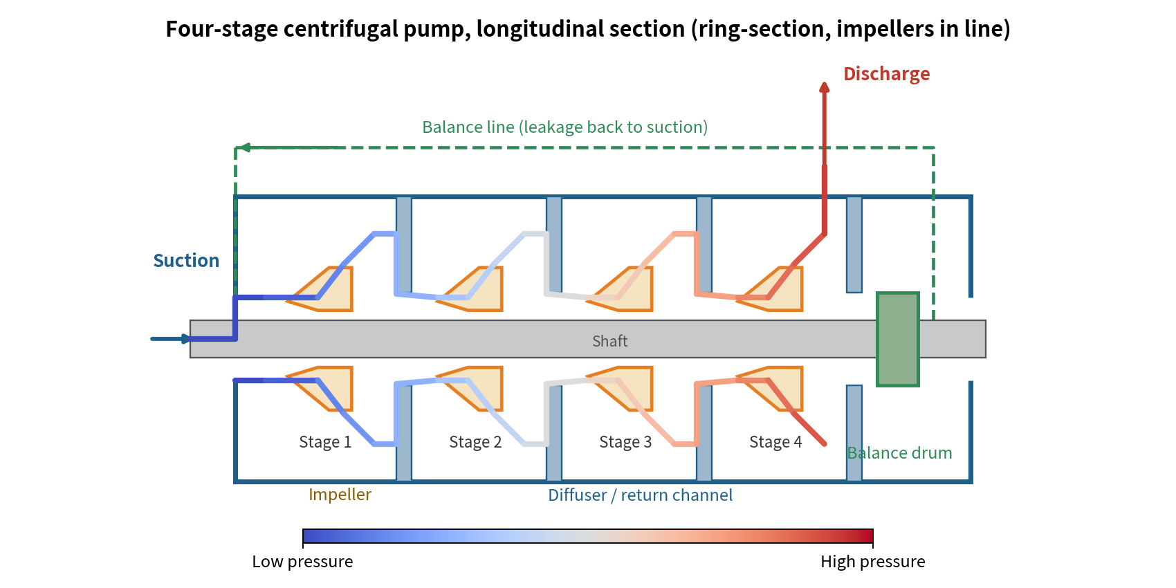
Figure 4. Four-stage centrifugal pump, longitudinal section (ring-section, impellers in line; original simplified schematic).
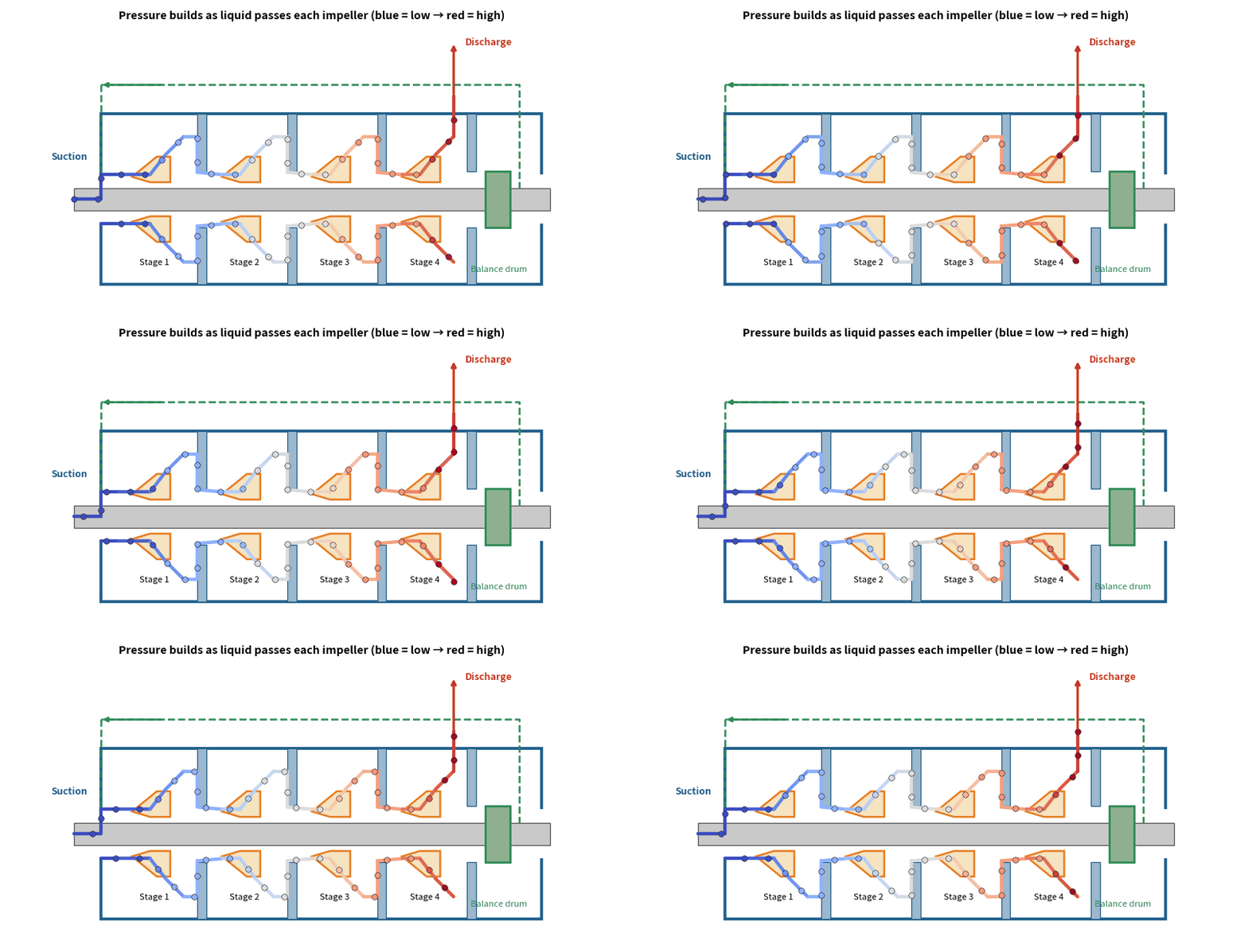
Figure 5. Animation: liquid gains pressure stage by stage (animated GIF — plays in Word; a standalone GIF file is supplied too. Blue = low pressure → red = high pressure).
4.1 Why Use Multistage: A Worked Example
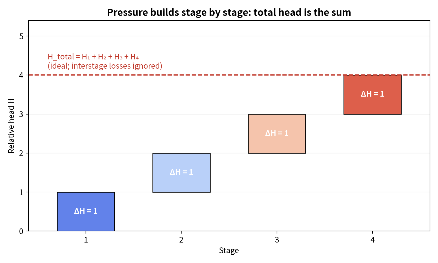
Figure 6. Pressure builds stage by stage: total head is the sum of the stage heads.
Worked example (illustrative data): five stages of 60 m each give an ideal total head of about 5 × 60 = 300 m (interstage losses reduce this slightly in practice). For Q = 30 m³/h = 0.00833 m³/s of clean water (ρ ≈ 998 kg/m³), hydraulic power P_h = ρ·g·Q·H ≈ 998 × 9.81 × 0.00833 × 300 ≈ 24.5 kW; at a pump efficiency of 65% the shaft power is about 24.5 / 0.65 ≈ 37.7 kW. Reaching 300 m with one impeller would need a very high speed or a very large diameter, with unacceptable stress, cavitation and noise — which is exactly why multistage pumps exist.
Typical uses: boiler feed, pressure boosting for tall buildings and long water mains, mine dewatering, reverse-osmosis feed, pipeline boosting and many high-head process services.
4.2 Flow Path and Main Parts
- Suction chamber: guides liquid evenly to the first-stage impeller eye. The NPSH requirement of a multistage pump is governed mainly by the first-stage inlet, so NPSHR must still be checked (Section 6).
- Impellers: mounted one after another on the same shaft; each stage adds its share of head.
- Diffuser / return channel: slows the fast liquid leaving the impeller to recover pressure, then guides it radially inward to the next impeller eye. [8][23]
- Interstage diaphragms and seals: separate neighbouring stages at different pressures; throttling bushes or wear rings limit leakage from high to low pressure, and their wear reduces efficiency just as with ordinary wear rings. [24]
- Balancing device: cancels the accumulated axial thrust (see 4.4).
- Discharge casing: collects the last-stage flow and sends it into the discharge line.
4.3 Three Common Casing Constructions
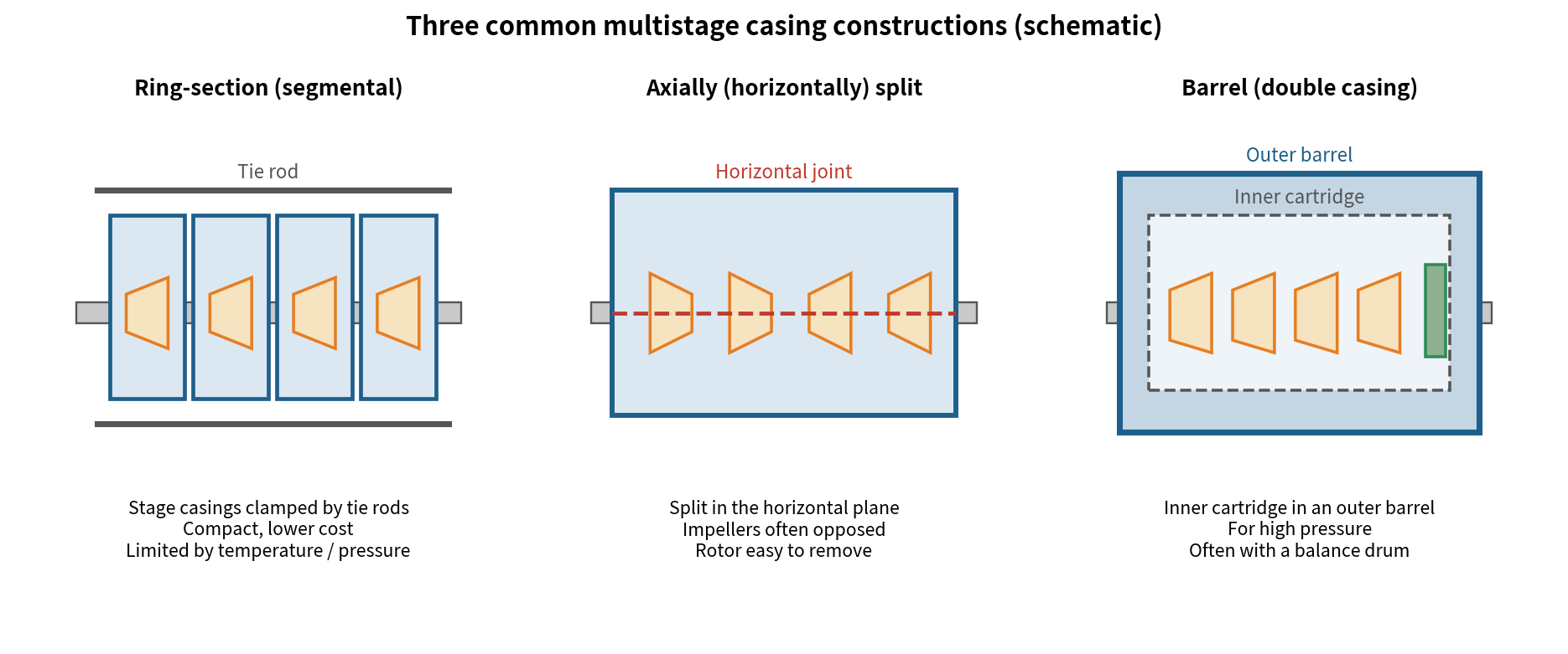
Figure 7. Three common multistage casing constructions
Type (API 610 Code)
Construction
Advantages
Limitations
Ring-section / Segmental (BB4)
Axially (Horizontally) Split (BB3)
Barrel / Double Casing (BB5)
4.4 Axial-Thrust Balancing: The Key Design Issue
The pressures acting on the two sides of each impeller differ, producing an axial force toward the suction side. In a multistage pump, with high pressure and many impellers, these forces accumulate into a very large load that would quickly destroy the thrust bearing if left untreated. [23] Two main solutions are used:
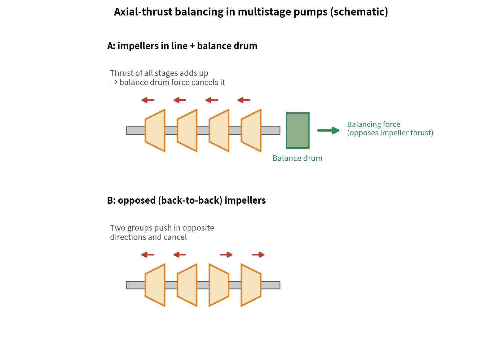
Figure 8. Two ways of balancing axial thrust in a multistage pump
Method
How It Works
Notes
Opposed (back-to-back) Impellers
Balance Drum / Disc
Maintenance note: the balancing device works through very small clearances; when they wear, leakage rises, balancing force falls and thrust-bearing load increases. Engineering sources warn that if a balance drum / disc fails, thrust-bearing failure is likely to follow. [25] Watch balance-line flow, thrust-bearing temperature and shaft position, and check clearances as the manufacturer requires.
4.5 Operation and Maintenance Points
Point
Explanation
Prime and vent before start-up
Minimum Continuous Flow
Speed Control
Interstage Clearances
Vibration and Shaft Position
4.6 Single-Stage or Multistage?
Aspect
Single-Stage
Multistage
Head
Complexity
Footprint and Cost
Axial Thrust
Typical Uses
5. Classifying Centrifugal Pumps
Pumps can be classified in several ways, and a real selection normally uses several at once.
Basis
Types
Notes
Number of Impellers
Impeller Inlet
Shaft Orientation
Casing Joint
Flow Collection
Pressure Class (Textbook Convention)
Liquid Handled
In the oil, petrochemical and gas industries, API 610 / ISO 13709 groups centrifugal pumps broadly into overhung (OH), between-bearings (BB) and vertically suspended (VS) types, then subdivides them. [22]
6. Cavitation and Air Binding: Similar Symptoms, Different Problems
6.1 Cavitation
- Mechanism: when local pressure at the impeller inlet falls below the liquid’s vapor pressure at its operating temperature, vapor bubbles form. Carried into a higher-pressure region, they collapse violently; the surrounding liquid rushes into each void and produces local shock loads. Repeated impacts on the impeller and casing cause pitting, cracks and, in severe cases, a sponge-like loss of material. [2][3]
- Symptoms: noise (often described as gravel rattling in the pump), vibration, falling flow / head / efficiency — in extreme cases no delivery at all — and pitting near the impeller inlet.
6.2 Understanding NPSH: NPSHA vs. NPSHR
- NPSHA (available): set by the installation; it is how far the liquid’s total head at the pump inlet exceeds its vapor-pressure head.
- NPSHR (required): set by the pump, determined by test and published on the performance curve. In the standard HI test, suction pressure is lowered step by step at constant speed and flow until pump head falls by 3% relative to the cavitation-free value; the corresponding NPSH is NPSHR (NPSH3%). [1][3]
Calculating NPSHA (Open Supply Tank, Pump Above the Liquid Level)
NPSHA = (p_atm − p_v) / (ρ·g) − Z_s − h_f
p_atm: absolute pressure on the liquid surface; p_v: vapor pressure at the pumping temperature; ρ: density; g = 9.81 m/s²; Z_s: height of the pump inlet centre above the liquid surface (positive for suction lift, negative for flooded suction); h_f: total suction-line losses including valves, bends and strainers.
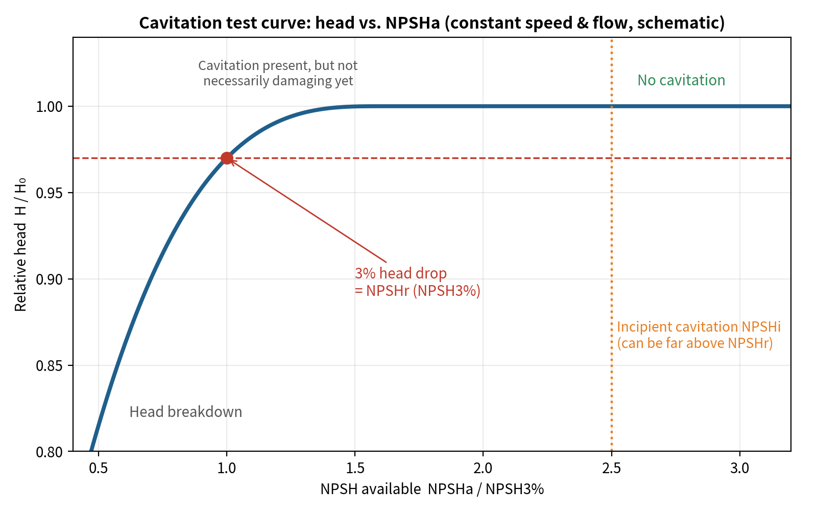
Figure 9. Cavitation test curve: head vs. NPSHA at constant speed and flow
Important Correction: NPSHA > NPSHR Does Not Mean “No Cavitation at All”
The Hydraulic Institute states that impellers can still cavitate when NPSHA exceeds NPSHR, though this does not necessarily damage the impeller; damage also depends on liquid thermodynamic properties, materials, running time and other factors. [1] Industry authors report that cavitation can begin at 2 to 20 times NPSHR, averaging about 4–5 times. This does not mean NPSHA must be 4–5 times NPSHR, but a reasonable margin is needed. [2] The HI also publishes NPSH-margin guidance by application type and suction energy; consult it when selecting pumps.
6.3 Worked Example: Same Piping, Water at 20 °c Vs. 80 °c
Given (example data): open supply tank, p_atm = 101.3 kPa; pump inlet 3.0 m above the liquid surface; suction-line losses h_f = 0.8 m; pump NPSHR = 3.5 m at the duty flow. Water vapor pressure and density are taken from steam tables. [21]
Case
Water, 20 °C
Water, 80 °C
p_v
ρ
(p_atm − p_v)/(ρg)
NPSHA
Versus NPSHR = 3.5 m
Conclusion: the temperature rise alone raises vapor pressure so much that NPSHA falls from about 6.3 m to about 1.9 m, below what the pump needs. Fixes: cool the liquid, lower the pump (or move to flooded suction so Z_s becomes negative), enlarge the suction pipe to reduce h_f, or choose a pump with lower NPSHR.
Water Temperature
Saturation Pressure (kPa, Approx.)
20 °C
60 °C
80 °C
100 °C
6.4 Air Binding
Mechanism: if air is trapped in the pump at start-up, its very low density means the impeller generates little centrifugal force and little pressure difference; the low pressure at the eye is not enough to draw liquid in, so the pump spins without delivering. This is why an ordinary centrifugal pump has no self-priming ability and must be filled with liquid before starting (or have its suction placed below the liquid level so liquid flows in by gravity).
6.5 Cavitation vs. Air Binding
Aspect
Cavitation
Air Binding
Nature
When it Occurs
Typical Signs
Basic Remedy
Damages the Impeller?
7. Prevention Checklist
7.1 Cavitation: Causes and Remedies
Common Cause
Remedy
7.2 Air Binding: Causes and Remedies
- Fill the casing with liquid and vent all air before starting; priming valves and connections must be tight.
- Fit a foot valve on the suction line (to keep the primed liquid in) and a strainer (to stop solids); check suction flanges and the stuffing box for air leaks.
- Place the pump inlet below the liquid level so liquid flows in by gravity (flooded suction).
- Keep enough submergence at the suction inlet so vortices at the surface cannot draw in air.
- Fit a regulating valve in the discharge line for starting, stopping and flow adjustment.
8. Start-up, Shut-down and Operating Adjustments
8.1 Start-up Checklist
- Check the pump, motor, foundation bolts and coupling alignment; the shaft should turn freely by hand.
- Confirm lubricant grade and level; check the shaft seal (gland tightness or mechanical-seal flush)
- Open the suction valve fully; prime the pump and vent all gas.
- With the coupling disconnected, bump the motor and confirm rotation matches the arrow on the casing (a reversed pump can loosen a lock nut).
- Most radial-flow pumps are started with the discharge valve closed or slightly open (lowest power demand); open it slowly to the duty flow after starting. Do not run closed for long — the liquid heats up.
- While running, monitor current, discharge pressure, bearing temperature, vibration, noise and seal leakage. Never use the suction valve to adjust flow.
- To stop, close the discharge valve gradually and then stop the motor; deal with any liquid left in the pump as the service requires.
These are general practices; always follow the pump manufacturer’s installation, operation and maintenance manual (IOM).
8.2 Adjusting the Duty: Affinity Laws
When the speed n of the same pump is changed, flow, head and shaft power approximately follow: Q₂/Q₁ = n₂/n₁; H₂/H₁ = (n₂/n₁)²; P₂/P₁ = (n₂/n₁)³. Cutting speed by 20% (n₂/n₁ = 0.8) gives about 80% of the flow, 64% of the head and 51% of the power — the basis of the energy savings from variable-speed drives. NPSHR also falls as speed is reduced. These are approximations; for large speed changes or systems dominated by static head, check against the system curve.
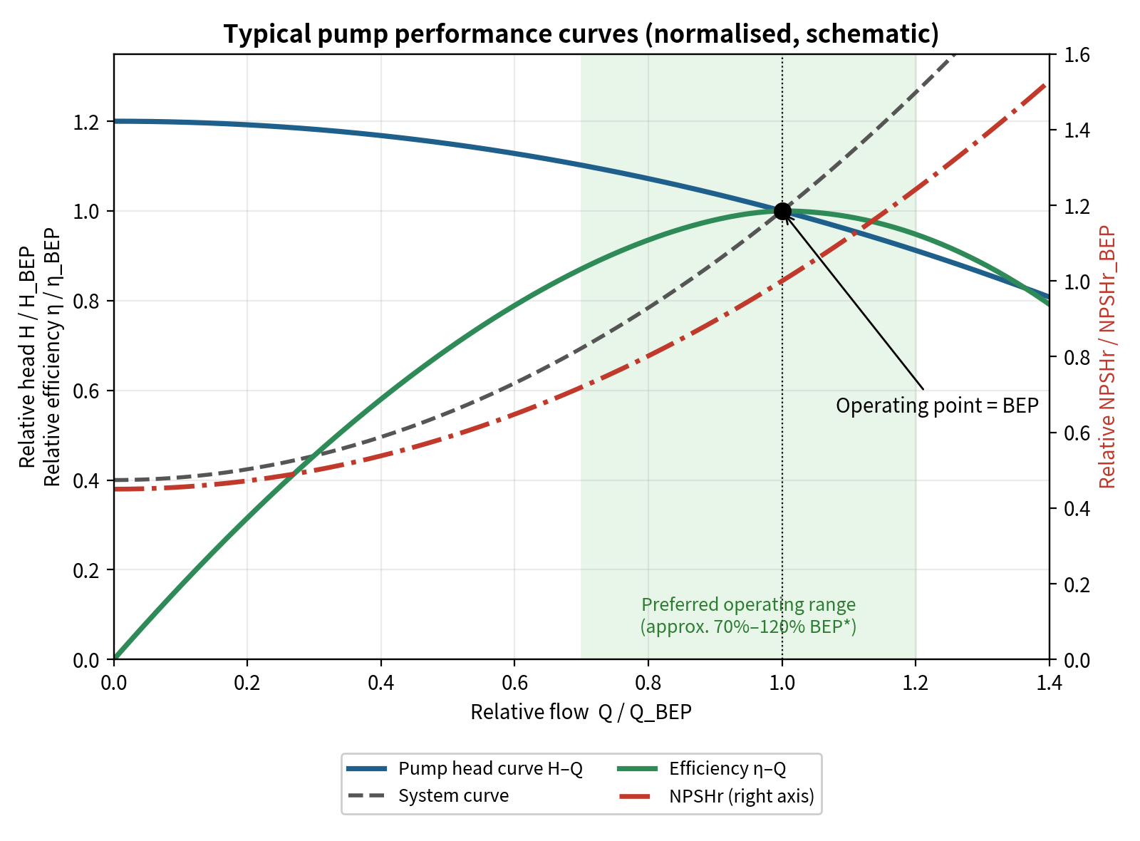
Figure 10. Typical performance curves and preferred operating region (normalised schematic; *preferred region per ANSI/HI 9.6.3, about 70%–120% of BEP flow for most pumps).
Reading the chart: (1) the intersection of the head curve and the system curve is the real operating point; (2) the peak of the efficiency curve is the BEP, which the operating point should stay close to; (3) NPSHR rises with flow, so higher flows make cavitation more likely. HI’s preferred operating region (POR) is generally 70%–120% of BEP flow, narrowing to 80%–120% for higher specific speed pumps; API 610 additionally requires rated flow to lie within 80%–110% of BEP. [13]
9. FAQ
Q1: The pump will not deliver. What do I check first?
Confirm it is primed and vented (air binding), then check for suction-line air leaks, a blocked foot valve or strainer, correct motor rotation, and an excessively low supply level.
Q2: There is a gravel-like rattle and flow has dropped. What is it?
Classic cavitation. Recalculate NPSHA against NPSHR and check suction resistance, liquid temperature and whether flow is too high.
Q3: Can I throttle the suction valve to reduce flow?
No. Keep it fully open; throttling lowers inlet pressure and invites cavitation. Adjust flow with the discharge valve, speed, or impeller trimming.
Q4: What happens when wear rings wear?
Internal leakage rises, so delivered flow and efficiency fall; replace them once clearance exceeds the specified limit (for example about twice the new minimum).
Q5: Single or double volute?
A single volute is common when high efficiency and clean liquid matter; consider a double volute for wide flow ranges or to reduce radial loads on bearings and seals, remembering its splitter vane can clog with solids. [5]
10. Corrections to Common Statements
So that every statement can be checked, the following common claims were corrected or qualified, with the basis noted:
Common Statement
How It Is Treated Here
About the Figures and Sources
Figures 1–10 are original schematics, not photographs; the curves show normalised trends, not measured data for a specific pump. For real data, use the manufacturer’s performance curves.
References
[1] Hydraulic Institute. Pump FAQs (January 2007) — cavitation when NPSHA > NPSHR, the 3% head-drop criterion for NPSHR, and ANSI/HI 1.6. Pumps & Systems. https://www.pumpsandsystems.com/?p=4547
[2] Budris, A. R. Understanding Pump Cavitation and Its Impact on Pump Reliability. WaterWorld. https://www.waterworld.com/wastewater/treatment/article/16193748/understanding-pump-cavitation-and-its-impact-on-pump-reliability
[3] KSB. Centrifugal Pump Lexicon: NPSH. https://ksb.com/en-global/centrifugal-pump-lexicon/article/npsh-1116954
[4] Ruhrpumpen. Understanding Pump Cavitation. https://www.rcworst.com/blog/Understanding-Pump-Cavitation
[5] Budris, A. R. Pump Protection: The Pros and Cons of Various Centrifugal Pump Casing Types. WaterWorld. https://www.waterworld.com/wastewater-treatment/article/16190692/pump-protection-the-pros-and-cons-of-various-centrifugal-pump-casing-types
[6] Hydraulic Institute. HI Pump FAQs (February 2014): Single-Volute & Double-Volute Casings. Pumps & Systems. https://pumpsandsystems.com/hi-pump-faqs-february-2014
[7] Mina, E. M.; Abdelmessih, R. N.; Matbouly, M. E. Reduction of Radial Thrust by Using Triple-Volute Casing Centrifugal Pump. Journal of Al-Azhar University Engineering Sector, 11(38), 2016, 115–124. https://journals.ekb.eg/article_19501.html
[8] Pump Industry (Australia). Centrifugal pump basics (casings, radial thrust, diffusers). https://www.pumpindustry.com.au/?p=7513
[9] EASA. Wear ring considerations for centrifugal pumps. https://easa.com/resources/resource-library/wear-ring-considerations-for-centrifugal-pumps
[10] Pumps & Systems (2019). Wear Ring Clearance for Centrifugal Pumps. https://pumpsandsystems.com/wear-ring-clearance-centrifugal-pumps
[11] Goulds Pumps 3700 IOM — Minimum running clearances / replace wear rings. https://www.manualsdir.com/manuals/461697/goulds-pumps-3700-iom.html?page=75
[12] Pumps & Systems. Effect of Internal Clearances on NPSHR. https://www.pumpsandsystems.com/effect-internal-clearances-npshr
[13] Pumps & Systems. Pump Selection: Understanding Manufacturer Family Performance Charts, Part 1 (POR/AOR in ANSI/HI 9.6.3 and API 610). https://www.pumpsandsystems.com/pump-selection-understanding-manufacturer-family-performance-charts-part-1
[14] Wilo USA. Best Efficiency Point (Pump Basics). https://wilo.com/us/en_us/Training/On-Demand-Resources/Pump-Basics/Best-Efficiency-Point/
[15] AESSEAL. Why use mechanical seals (packing vs. mechanical seal). https://www.aesseal.com/en/resources/academy/why-use-mechanical-seals/
[16] SEPCO. What Is a Stuffing Box? A Beginner’s Guide to Pump Maintenance. https://empoweringpumps.com/sepco-what-is-a-stuffing-box-a-beginners-guide-to-pump-maintenance
[17] Pumps & Systems. Impeller types: semi-open impellers, axial force and pump-out vanes. https://www.pumpsandsystems.com/?p=7489
[18] Pump Industry (Australia). Selecting the correct sewage pump impeller. https://www.pumpindustry.com.au/selecting-the-correct-sewage-pump-impeller/
[19] Wikipedia. Impeller. https://en.wikipedia.org/wiki/Impeller
[20] Carver Pump Company. Impeller Selection: Semi-open vs. Enclosed. Environmental Expert, 2021. https://www.environmental-expert.com/articles/impeller-selection-semi-open-vs-enclosed-1019451
[21] NIST Chemistry WebBook / IAPWS-IF97: saturation properties of water (steam tables). https://webbook.nist.gov/chemistry/fluid/
[22] Related standards (consult the official texts): ANSI/HI 1.6 (centrifugal pump tests); ANSI/HI 9.6.1 (NPSH margin guideline); ANSI/HI 9.6.3 (allowable / preferred operating region); API 610 / ISO 13709 (centrifugal pumps for petroleum, petrochemical and natural gas industries); API 682 (shaft sealing systems).
[23] EPO patent publication EP 3889434 A1. Multistage centrifugal pump with a balancing line… (background on multistage construction, ring-section / barrel types, balance drum and balance line). https://data.epo.org/publication-server/rest/v1.2/publication-dates/20211006/patents/EP3889434NWA1/document.html
[24] Pumps & Systems. Multistage pump types (BB3 axially split, BB4 ring-section, barrel) and thrust balancing. https://www.pumpsandsystems.com/?p=8274
[25] Eng-Tips Forums FAQ. Balance drum / disc and opposed impellers in multistage pumps (engineers’ forum — reference only). https://www.eng-tips.com/faqs.cfm?fid=1306